Nixie clock


One might know them from the bomb-defusing scene in the Bond movie "Goldfinger" or the Divergence Meter from Steins;Gate.
In short, its ten(0-9) wires glowing neon yellow in a vacuum tube, first replaced by seven-segment displays, they are becoming increasingly popular nowadays, because of their beauty.
There are quite a lot of kits available online, but there is the fun in buying one?
Designing the Circuit:
The difficulty in it lies in the operating voltage of a Nixie-clock: ~170V
So I decided to use two circuits, one high-powered circuit driving the tubes and one low-powered one for switching the power to the digits on and off.
For switching, I used a quite common shift register, the SN74HC595DR
some 20k Ohm resistors and high-power transistors.
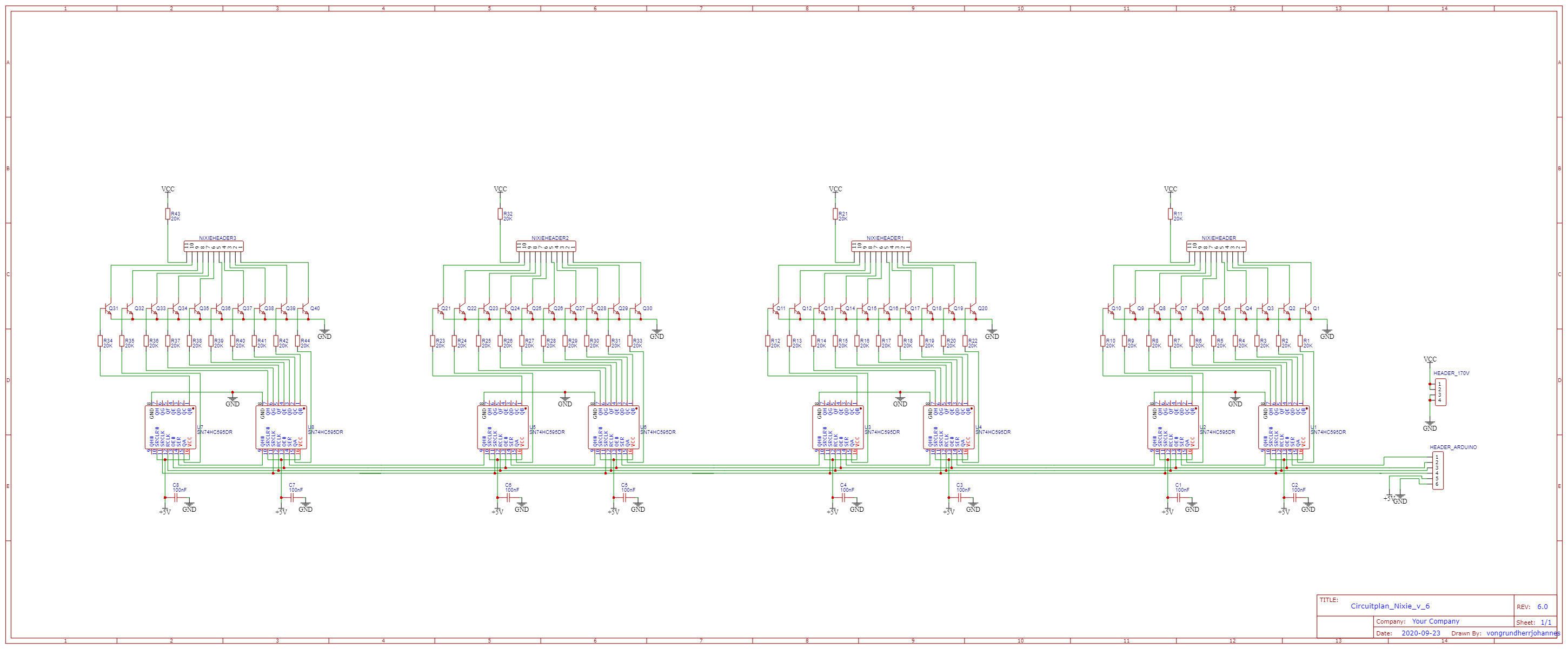
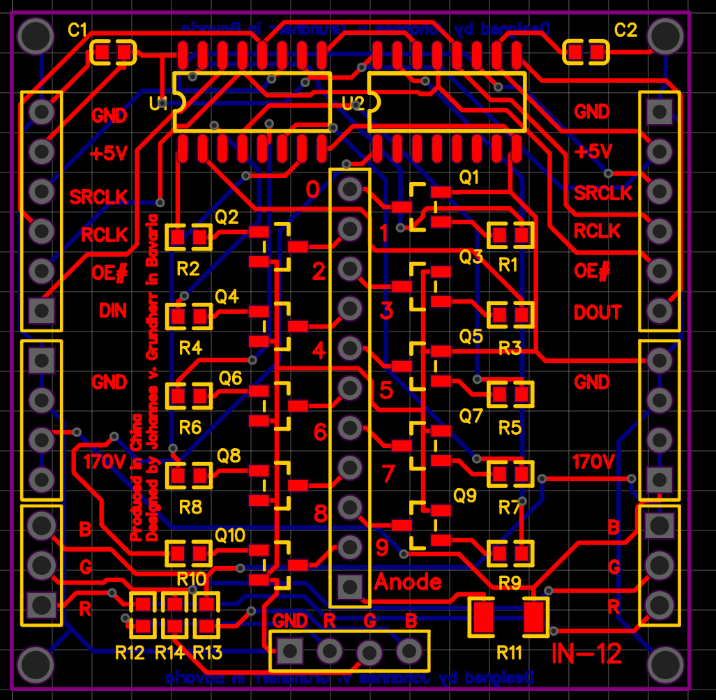
As you may see, using a shift register allows us in theory to daisy-chain as many tubes together as we like to, therefore I tried to make the pcb as modular as possible, with the input on the left and output on the right:
Note: I added the RGB just for the sake of doing it, having LEDs under a Nixie clock is pure blasphemy.
Making it Real:
Since most of the parts are SMD components, which are too hard to solder by hand, I switched to EasyEda mid-development, because they had a list of parts, which JLCPCB could assemble, while redoing the layout, a little mishap happened:
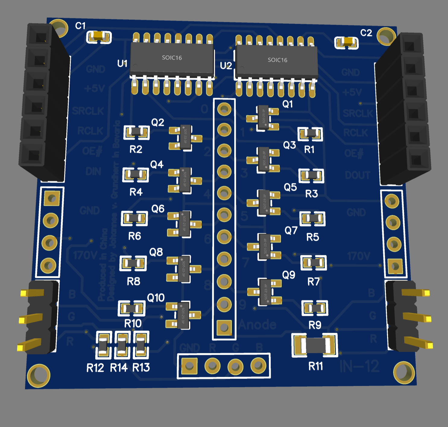
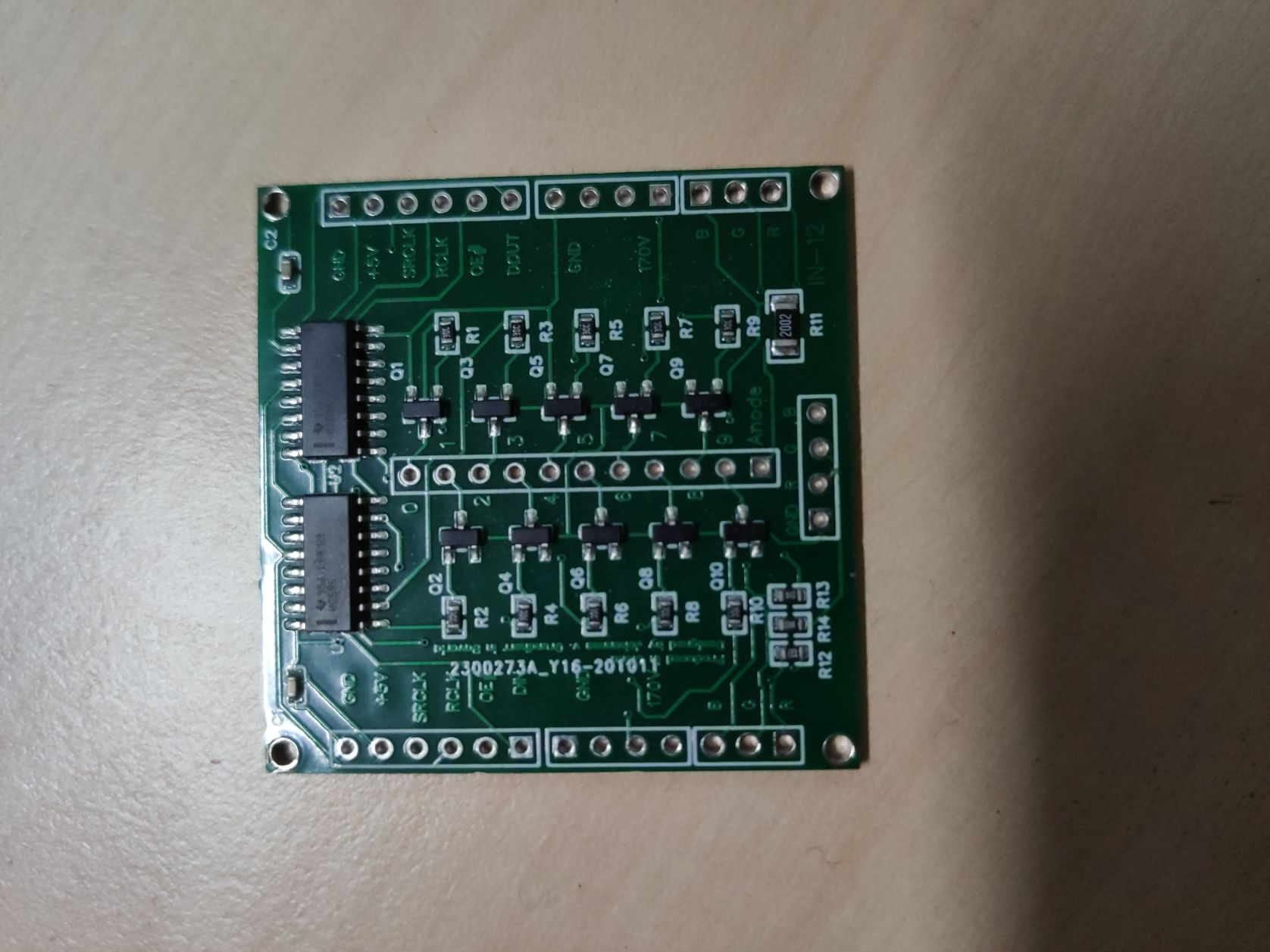
The description was in the solder mask and not the silkscreen mask... F
Apart from that, it turned out great:
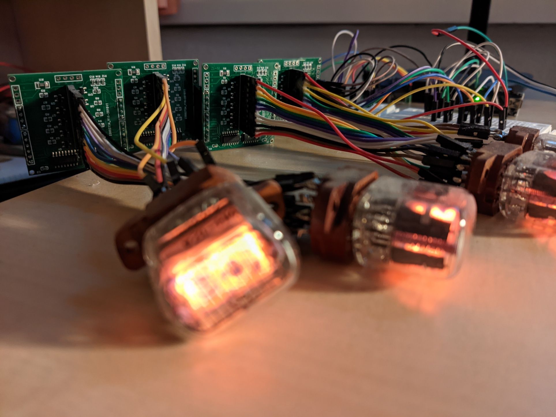
Now for the moment of truth, does it actually work?
For driving the shift registers I used an Arduino Nano and for the 170V circuit a high-power supply from Ebay.
See for yourself:
Since it looks rather barebone for now, my plan was to go to my local FABLAB @FAU and build a case out of wood for it, but since it's not exactly spacey in there, it has been closed since the pandemic began, so this project is not finished for now.
To be continued...